

Publication: Heat Treating Progress, July/August 2004
Author: Fred R. Specht, Ajax TOCCO Magnethermic Corp, Warren, Ohio
It’s important to be mindful of some basic tips when induction heat treating parts. Attention to certain process details will keep the results of your process consistent and within specified tolerances.
The process of induction provides exact repeatability from one part to the next. Proper setup is required to duplicate previous pattern and hardness results with acceptable limits, whether it’s done by experienced personnel or by novices. The importance of repeatable setup cannot be stressed enough. setups can take from 2 to 10 minutes on properly designed equipment. Coils can be designed to produce a lifetime of repeatable setups without the use of tools. Controls can be as simple as operating a home computer. These factors make induction hardening and tempering the process of choice for most engineers that face the tough cost competition of today’s global markets.
Figure 1. – Coil support tabs help prevent tubing-type coils from moving or being damaged.
 Repeatable setups
The setup is the starting point from which to consistently achieve patterns and hardness within acceptable limits. The position of the workpiece within the coil, the precise amount of power, the quench volume, and exact placement of the quench play important roles in the resulting hardness pattern.
Many coils use quick disconnects to allow fast, easy changeover. Water connections can be made. Water connections can be made with quick-connect hoses or O-rings. O-rings limit inductor adjustment and can be a source of water leaks. Use of petroleum jelly on O-rings can help seal them and hold them in place. Quench hoses should use "Hansen" quick couplings to connect to the coil. Use a different size coupling for quench water than for coil cooling water to eliminate the possibility of getting the hoses confused.
Tooling cups and centers for part support should require no tools to change, yet should be rugged enough to steady the part.
Newer induction systems have a precise control system that stores recipes for each part. Password-protected operator control systems are available to prevent anyone from altering the recipe. The setup sheet and the system control recipe should yield a good part from one setup to the next. This starts with the accurate coil/workpiece relationship.
A rugged coil, quick disconnect, bus work, and fixture are of great importance in achieving repeatable setups.
Coils Can Last A Lifetime
Machined integral quench coils are the most expensive type. However, they generally last longer. Tubing-type coils are the least expensive, but can be bent with the bare hand around a mandrel. Tubing coils may need added support to prevent them from moving as a result of the mechanical forces exerted on the copper during induction heating. These forces are a function of power density and frequency, coupling to the workpiece and other turns of copper, and copper fatigue. Radio frequencies usually do not exert a mechanical force great enough, but coil tabs and gussets should still be used to prevent the copper from bending during handling. Many RR coils are made of small (0.25″ or 0.5″) copper tubing. These are extremely fragile without support gussets and tabs (Figure 1). Several brass screws brazed to the separate turns, with corresponding nuts and washers, will prevent movement of the turns during setups. The coil turns can be adjusted during development and then locked into place. This makes it easy to make initial adjustments and repeat the position of the coil relative to the workpiece thereafter. Well-designed, rugged tooling used for a setup should result in an acceptable pattern and thus should not become an experiment for each setup.
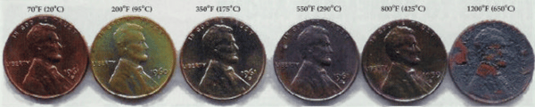
Figure 2 – Pennies discolor at various temperatures. Copper coil discoloration can be a diagnostic tool to ID problem areas.
 Coil Cleaning:
Cleaning the inductor after every use will remove polymer quench and scale before they dry. It is relatively easy to clean while the inductor is still wet, but the polymer quench and scale will eventually “bake on” and become difficult to remove. Having a clean, shiny coil for diagnosis of cooling problems is important. The copper discolors at high temperatures and this discoloration can be a diagnostic tool to identify specific problem areas. In Figure 2, the copper U.S. cent chart shows varying copper discoloration that occurs at different temperatures.
Every six months, the internal water cooling path of the coil should be flushed with Lime-A-Way (Reckitt Benckiser Inc., Wayne N.J.), CLR (Jelmar, Skokie, Ill.), or a dehumidifier-type cleaning solution. This will remove internal buildup of calcium deposits that precipitate out of the water at 135°F (55° C). These solids take the form of a white, powdery residue that adheres to the inside of the coil cooling path. This is similar to the residue left inside a pot after water has boiled off. The residue insulates the copper from releasing heat through the water, causing the coil to run hotter until it fails prematurely. This is seen in high-power-density applications, especially with lower-efficiency coils such as pancake-type, ID hardening, and tooth-by-tooth coils. On ID-hole applications, the failure often occurs on the inside leg (down the center). This is where the water temperature is hottest. Make sure the water path enters down the center leg first on the ID coils. Flow can be increased and additional heat removed by the addition of a booster pump in the coil water circuit. If the coil is discolored, especially down the center leg, it is from overheating. In such a case, more water cooling or a lower power density is required.
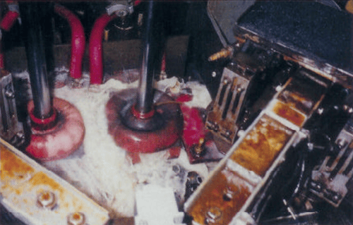
Figure 3. – Quenchant is diverted by simple cones, preventing overspray.
 Quench is everything!
For consistent hardness results, check the polymer percentage every morning with a refractometer after the quench pump has been on and recirculating for a few minutes. This is done before any heat treating takes place and will stir the quench to yield an accurate percentage reading. It will also remove any air trapped in the quench lines. Use a timed quench-temperature heater, set up like a programmable home thermostat. This turns on the heater in the morning an hour or so before you plan to start production to ensure that the first part sees the proper quench temperature.
The quenchant temperature should be automatically controlled with a heat exchanger and solenoid valve. Temperature variation greater than 10°F (6°C) may result in more-than-expected distortion or even a crack in the workpiece.
The volume, or flow rate, of quenchant is extremely important. The more quenchant, the faster the part can be processed. Spray shields, doors, and enclosures should prevent the operator from getting wet and prevent quenchant buildup on the floor. The shields need to be placed very close to the coils in single-shot applications. The shield can be as simple as a piece of clear PVC pipe. The less quenchant splashed on machinery, the easier maintenance is accomplished. In scanning applications, flanges and the resulting upward spray can be restricted by adding simple plastic cones upside down to divert the quenchant back down, as shown in Figure 3.
Never place rag-type shields in the quench area, as the polymer attacks it and devolves the rag into the quenchant. As a result, the small holes in the quench barrel may become clogged, and higher pressure and less quenchant comes out of one side of the quench barrel than the other. Uneven quench is a cause of distortion and low, uneven hardness. This can show up as excessive total indicated runout (TIR) and collapse the size of ring grooves and keyways.
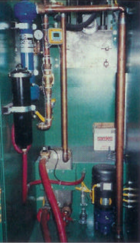
A removable, easily cleaned quench faceplate can be incorporated into the same designs. If the quench head is continually being clogged, it usually means a bigger problem exists in the bottom of the quench tank. Scale from the heat treating process is a natural occurrence in carbon steel. Scale can clog quench holes and can be removed by bag or bed filters. Full-flow bag filters generally are used in extreme cases of scale buildup, such as hardening hot rolled or forged steel surfaces (Figure 4). Scale is abrasive and erodes holes.
Figure 4. – Quenchant filtration with separator and bypass bag filter to remove scale from quench systems.
 Plugged Holes
Quench barrels and integral coils should have at least four water inputs for even quenchant distribution. If in doubt, stick your hand into the quench barrel and feel the sides to see if there is more force on one side than the other. (Before doing this, make sure that the power supply is off, the workpiece has been removed, and the quench is set on manual.) An uneven quench will result in more distortion. Use a standard ball valve to adjust for even flow around the quench.
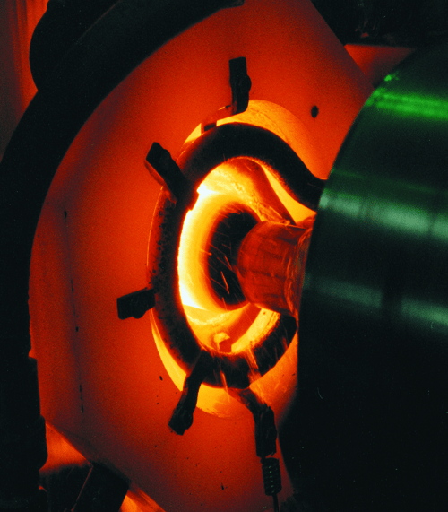
In scan heat treating applications, the quench impingement point is of utmost importance. If a single hole in the quench head is off its correct angle, it can cause a barber pole effect. Sometimes foreign matter can become lodged in the hole and cause the same effect. The smaller the diameter of the workpiece, the more important impingement is. For deeper case requirements, quench impingement can be further away from the coil. The more shallow the case, the closer the impingement point should be to the 1600°F (870°C) surface (Figure 5).
If the quench has a bad smell, it is growing fungi. Agitation or operation of the pump will oxygenate the quenchant and usually kill the fungi and the smell. This is only a quick fix, as the smell will come back when the pumps are shut off for a while. Disposal and cleaning should be done every 6 to 12 months, or as recommended by the manufacturer. Check with your quenchant supplier.
Never use the quench tank as a parts washer. Chips and tramp oils can foul the polymer quenchant. These chips cause the ground detector system to make unnecessary production stops. Heat treaters throw out thousands of dollars worth of quenchant due to carry-over contamination. Oils and lubricants used in grinding, cutting, broaching, honing, drilling, and extruding, and the use of die lubricant, can cause this contamination. As the quenchant becomes more contaminated, the cooling curve changes. A slower quench results in progressively lower hardness or more distortion.
Figure 5. – Quench impingement point at bottom of red heating ring.
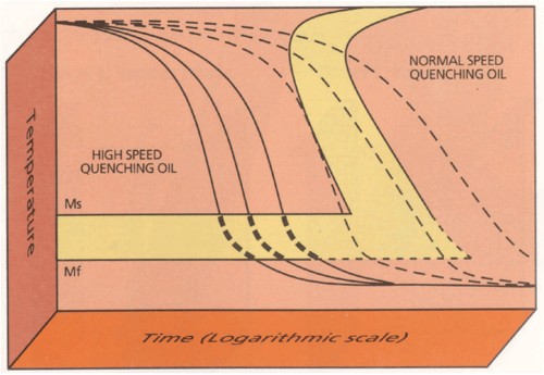
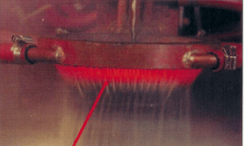 Figure 6. – Cooling curves for fast oil versus slow oil. The curves can be used to analyze contaminated quenchants. Courtesy Houghton International Inc., Valley Forge, Pa.
 Contamination
I have been told many times, “We get good hardness for a day or for a week, and then hardness falls out of acceptable limits. Then we change the quenchant and hardness jumps five points.” This is not magic. The cooling curve or the rate (speed) at which the steel quenches out is slowing. The cleaning and addition of new quenchant establishes a higher quench rate and hardness is high again. This slowing of the cooling curve can cause more distortion. The slower the quench rate, the longer heat is retained in the workpiece, and even more distortion is caused. Sending a sample to your supplier (who usually offers testing free or for a nominal charge) is one way of analyzing and identifying the contamination. The supplier compares the cooling curves (Figure 6) and generates a computer printout of the report.
Refractometer readings of polymer quenchants are easier to check than the percentage reading of the more precise viscosity tube test. The viscosity test uses a tube filled with quenchant and a stopwatch. This test shows exactly the percentage of polymer, but must be conducted by trained personnel. The refractometer test uses light reflected through a lens to yield a percentage. If the quenchant is contaminated by tramp oils or scale in the lens, the refractometer test yields incorrect results.
Refractometers are used in many other applications, such as checking antifreeze in a car and for rust inhibitors. Many refractometers used in checking quenchant percentages must multiply the reading by a factor of two. A reading of 4% in the window of the lens is really a reading of 8%. The higher percentage results in lower hardness than would be expected. It is ideal to have these instructions close to the operator. One possibility is to use a tie wrap and attach a laminated plastic card with the instructions about the multiplier onto the refractometer.
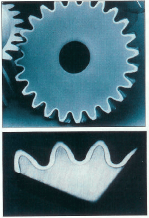
Figure 7. – Sandblasted heat treat pattern.
 Solving Distortion Problems
On scan or single-shot heating applications, a workpiece will not remain straight during heating and quenching if it does not remain straight during heating alone. This is usually due to pre-stresses in the part that are relieved during the heating process. If you are having distortion problems, try running the normal cycle without quench applied. Let the part air cool before you check for distortion. If your quench head is made out of PVD, you must remove it for the test, as the radiant heat will melt the quench head without quenchant running through it.
Give special attention to parts that require hardening over keyways or holes. To avoid overheating, melting, or cracking, keep adjusting the power down and scan speed up. Look closely as the part is actually heating. Only experience teaches what 1550°F (845°C) looks like! Once you have “the eye,” you can see the difference between 1550 and 1900°F (845 and 1040°C). For those just learning, temperature-sensitive sticks or paints work well. Paint small stripes of different temperature values (for example: 1500°F, 1550°F, 1650°F, 1800°F) in the area to be heated. Leave the quench off, and pay close attention to the part as it heats. You will see the paint actually melt and change color. If the paint does not change color, then the temperature was never achieved.
Never attempt to induction harden frozen workpieces. The parts should be at room temperature. Your part recipe is based on material at 70F (20°C) heating to 1550°F (845°C). If frozen material is processed, the same power input will yield a lower final temperature and full hardening transformation may not occur.
Induction Tempering
Induction tempering using the single-shot process is usually done with a high volume of parts because of the time spent on developing the recipe and the additional cost of equipment. Hardening cycle times can more than double when scan tempering is added.
Small lots of parts of similar steel grades can all be set in a basket and placed in the same oven at the same temperature at a lower cost than induction. In the cell approach to manufacturing, induction tempering is a valuable tool, providing the material can be quenched immediately after tempering to a consistent temperature before the next manufacturing step. These subsequent steps may include grinding, turning, honing, and broaching. A room temperature workpiece is essential for tight tolerance sizing work. Do not attempt to develop a temper cycle until a good hardness pattern and acceptable as-quenched hardness are achieved.
During scan tempering process development, the workpiece is induction hardened, and at the end of the heating and quench delay, the part goes back beyond the original start point with a reduced power level and scan rate.
Make sure the part is allowed to cool to at least 150°F (65°C) after the hardening cycle before the temper cycle begins. This consistent workpiece temperature is essential to a good temper. Any residual temperature above 150°F (65°C) left from the hardening process will unevenly raise the temper temperature and affect the final hardness readings by several points. When developing temper recipes, usually no more than one-half to one-third of the hardening power is used to induction temper. The scan speed can be the same as hardening if the case is thin enough or a minimum hardness change is required.
Tempering, annealing, stress relieving, and normalizing are all ways to temper back original high hardness readings to a lowered specified hardness. A range of hardness values is usually specified by engineering for a particular application or use. AISI 1045 steel that quenches out at 60 HRC and requires a hardness of 60 HRC minimum does not technically require a temper. Good metallurgical practice does require at least a stress relieving at 300°F (150°C), which only drops the hardness one to two HRC points. Induction tempering temperatures usually need to be lighter than that for an oven temper to yield the same results, but from a hardness standpoint, these results are consistently comparable to ovens. Check your ASM Handbook, Vol. 4 on Heat Treating, or ASM’s Heat Treater’s Guide: Practices and Procedures for Irons and Steels for accurate tempering temperatures. The heat-sensitive sticks (points) are used for checking temper temperatures as well as during first-time recipe development.
Nondestructive Testing
Sandblasting, glass bead peening, and shot peening all can yield identifiable hardness patterns on the surface of a steel workpiece. These simple processes can bring out the heat treat pattern without the use of dangerous acids. It only takes seconds of sandblasting and "moments" of glass bead or shot peening to bring out a nice crisp heat treat pattern on a cut sample. You can spot-check production samples without the use of acids by having pattern lengths checked with a light sandblast. A $1000 investment in a 3′ x 3′ (1 x 1 m) sandblast booth can be much safer than handling the acids used in case depth analysis. The resultant pattern on the sandblasted sample lasts much longer than that on the acid-etched sample. The acid-etched pattern blackens over time and becomes unidentifiable because of residual acid (Figure 7).
Do not cut the sample workpiece unless the length of the pattern is correct. Use sandblasting to see the ends of the hardness pattern. Reuse the same setup pieces; they can be saved for the next setup. Fully anneal before reuse at 1000°F (540°C) and slow cool for reuse.
Hardness Readings
Do not be fooled by decarburization at the surface, this is like a dead skin surface and can result in erratic surface hardness readings. On rough-machined workpieces, grind to the finished size and check the hardness at the final depth and not the surface.
After heat treatment, look for suspicious rings with uneven colors – silver (hard) or blue (soft) that are more than 0.125″ (3.2 mm) wide. Check hardness across and between the rings for a soft barber pole effect.
One quick way to get a feel for a part’s hardness is to use a file. It does take some practice to become proficient at the use of files. Most purchased files are 65 HRC. You will need to temper each file at a different temperature. After slow cool, check with a Rockwell-type hardness tester and inscribe the handles with the corresponding hardness. This will result in a set of files of varying known hardness. A file that is 45 HRC will skate across a surface that is 55 HRC, yet will dig into a part that is 40 HRC. Files must be replaced as teeth wear off from use. The files are used as a quick surface check only, but they are especially useful in checking corners, flanges, and between gear teeth of large workpieces. Sets of these quick-check files are available on the internet.