
Background
Customer comments after observing the runoff of this crankshaft hardener prior to shipment were “I feel like I have just won the lottery,” “Impressive,” and “Every possible consideration for an improved machine and process has been incorporated into this system.”
Ajax TOCCO Magnethermic developed and introduced to the industry induction hardening of crankshafts over 75 years ago and over the years has shipped hundreds of crankshaft hardening systems. ATM has also supplied high-production automotive crankshaft hardening systems incorporating the critical requirement of fillet hardening. This concept originated in Europe approximately 50 years ago, and the Ajax TOCCO supply of high-production crankshaft hardening systems was with a European partner.
As the automotive market and the automotive equipment supply marketplace went global and became more competitive, the market demanded an improved solution; to remain a factor in the market required ATM to return to its roots and produce the entire system that met the market requirements.
This was put to the test in 2004 when a major truck manufacturer was searching for a supplier to provide equipment to harden a new V-8 crankshaft to be used in an all-new diesel engine.
The specifications were daunting:
- TIR – Eliminate or minimize straightening
- Auto temper integral to the process cycle
- Coil Life – Maximized
- Shoe Wear – Minimized
- Cpk the fillet hardened case depth
- And last but not least, successful equipment delivery with a proven process in less than one year
Benchmarking
A conventional crankshaft hardening machine would not be a viable re-entry into the market nor would it meet the defined requirements. ATM was determined to re-enter the market with the best possible equipment and process. With extensive crankshaft hardening experience and starting with a blank sheet of paper with respect to both machine design and process, all approaches were considered.
The existing global crankshaft hardening systems, fillet hardening coil designs, and transformer designs were benchmarked to establish a baseline starting point. Design improvements for all aspects of the systems and detail component designs were brainstormed to determine possible improvements. Where several alternatives appeared attractive, both or several were included in an experimental unit to test and evaluate the alternatives for the optimum choice for the final equipment.
Crankshaft hardening is the most challenging of the induction heat treating applications. Not only are there circumferential mass changes and changes in journal configurations and oil holes, but each part has multiple heat treated sections that all must be processed properly to meet the metallurgical and durability requirements. Conversely, the individual feature variability and multiple features greatly increase the probability of a rejected part.
The inductor design and the basic process have changed very little from the early days of development. There have been several attempts with non-rotational and non-contact approaches, but they have not been successful for fillet hardening applications.
The non-rotational approach, which recently was revived from the early developments, was eliminated because of the need to fillet harden; the non-rotational approach does not lend itself to fillet hardening. Another deterrent is that coil development is long and arduous, and the process is very inflexible. It is sensitive to crankshaft dimensional considerations in production and coil life can be an issue.
The non-contact approach does not follow the crankshaft distortion during heating, requiring generous clearances leading to even more heating and distortion, preventing the optimization of the pattern. Therefore it also was eliminated.
This analysis has definitely established that the rotational concept provided the unique flexibility to precisely program and profile the heating and quenching rate circumferentially to yield the optimum result and to adjust to variations that may occur in production.
Establishing “Best in Class”
ATM determined that the control and accuracy of the “conventional crankshaft hardening process” could be substantially improved with the advancement in control technology in servos and valves, process modeling, and solid-state IGBT power supply responsiveness. In essence, crankshaft hardening could be advanced from an experience-based technology to a science-based technology (i.e. going from an art to a science).
Many of the existing equipment approaches utilizing the conventional technology are difficult to maintain and have coil and shoe life issues. To avoid or minimize those effects, the following guidelines were established for the production system:
- The uptime of the crankshaft machine concept must meet the requirements of the associated in-line machine tools.
- Accessibility for maintenance is a major challenge on a crankshaft machine, but it must be improved from existing concepts.
- Inductor replacement must be simple, easily accessible, and allow for inspection after installation.
- Inductor life issues must be primary and all factors affecting inductor life must be optimized from the cooling system through coil design, inductor alignment, and motion-generated forces.
- Inductor shoe life must be improved.
- Distortion and dimensional control to meet the stringent straightness requirements to avoid straightening requires a flexible machine with process sequence and self-correcting options.
- Integral auto temper, which eliminates the tempering oven, reduces floor space and operating costs and must be implemented. All contributing variables must be controllable.
- The visibility of the process to the operator is essential for monitoring the operation and the refinement, fine-tuning, and maintenance of the crankshaft hardening process.
- The system must be capable of quality monitoring, assuring that each part is processed properly or rejected if it is not.
- All process variables must be profiled to assist in optimizing the metallurgy and TIR.
The machine concept was three individual stations to allow three individual processing steps, with all three stations capable of hardening up to five journals each and with any station capable of hardening any journal or group of journals. This allows for future changes in the sequence of hardening journals to correct for changes in the distortion as a result of changes in the prior process or a change in the crankshaft design.
The system included a TIR station between the last two stations to allow for adjustments in the process in the final station to minimize distortion if required and for the final measurement of TIR as a basis of rejection and or correction to the overall process to control distortion.
The customer considered robots to be the most reliable and flexible material handling technique in their facility. The robotic handling also allowed the machines to be accessible for process monitoring, maintenance, and coil exchange when required.
Accessibility, maintainability, and operational reliability were the primary criteria for the layout of the machine. Accessibility to the stations was allowed both in the front-load portion through the use of the robots and in the rear by spacing the power supplies and control panels away from the machine with transparent access doors for the machine, allowing the power supply HMI (Human Machine Interface) panels to be viewed along with the process.
Prototype Lab Development
Recognizing the interrelationship of the machine design elements and the process control requirements dictated a comprehensive prototype test facility. This was implemented to verify the process, equipment, and inductor design. A laboratory development unit capable of hardening all of the journals of one class (either pins or mains) was designed and manufactured.
The laboratory unit was equipped with a servo rotational axis, circumferentially variable power, pneumatic counterbalance cylinders and valves, and quench control valves. Signature analysis was used for coil voltage, coil current, coil power, and quench flow. It includes a TIR gauge to measure TIR on all five mains of a V8 crankshaft simultaneously, including TIR magnitude and direction.
After simulation analysis, the crankshaft development became an application of the scientific approach to develop the optimum process results as shown in Figure 1.
Figure 1. Process Development Procedure
The fillet hardening pattern was developed first for both mains and pins in the hardened condition as shown in Figure 2. This involved not only the selection of the coil copper and lamination configuration, but also establishing the power pulsing menu to properly profile the hardened pattern to accommodate the circumferential mass variations.
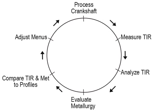
Figure 2. Typical Pattern
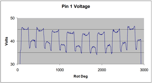
The power profiles were refined by monitoring the coil voltage (Figure 3) current and power; the power profiles were then compared to the heat-affected fillet depth and TIR and power and quench adjustments made as required as shown in Figure 1.
Figure 3. Typical Voltage Profile
In parallel with the hardening development, counterbalance techniques were developed to vary the counterbalance pneumatic pressure to minimize the force on the shoes to minimize shoe wear. The challenge was to find valves and a pneumatic system that could respond to the dynamics of the system as the crankshaft rotates at 30 rpm. Satisfactory components were located, installed, and experimentally verified.
Hardening each journal individually and establishing the vector contribution to distortion of each journal initiated the distortion development by utilizing charts as shown in Figure 4. Given the contribution of each journal, a sequence was established to minimize the final distortion. The results were quite amazing and exactly the opposite of the original hypothesis, illustrating the benefits of a scientific approach to establishing the process variables.
Figure 4. Typical TIR Station to Station Movement Vectors
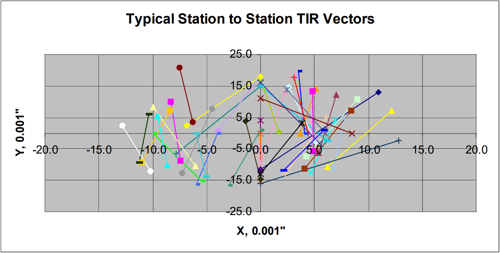
The customer requested parts with both low distortion and high distortion to evaluate the effects of straightening. Two groups of crankshafts were produced. The low distortion group averaged less than 0.015” TIR that did not require straightening, and by reversing the process sequence, a group was produced that averaged 0.030” for straightening.
Auto temper is a technique where the part is hardened to full hardness by quenching the hardened region below the Mf (martensite finish) temperature but leaving sufficient residual energy that restores the hardened region back to the tempering temperature. This requires very precise energy input, and likewise, very precise cooling. The mass variations in a crankshaft, especially a pin, are substantial, varying from the counterbalance portion of the pins adjacent to the mains to the TDC (top dead center) location that has very little mass.
The temper specification was based upon an oven temper result, which was to be attained with the auto temper process. Again, quench pulsing was studied, and it was determined to be required to precisely vary the quench circumferentially to attain the desired result. The same profiling technique used on the voltage, current, and power was employed for the quench. The quench flow was profiled and the response time of pneumatic valves and the pneumatic system studied with respect to the input signal and the resulting hardness to optimize the signal and allow for lags in the system so the desired flow was delivered to the desired region to increase or decrease the hardness.
The production of parts for fatigue testing and verification of the specification and the process completed the development project. The results obtained dictated the final design specifications for the production system.
Production System
With the criteria for the production system defined and with the specifications finalized, the production machine was completed.
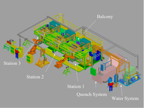
To allow the pantograph hanging assemblies to track the part, the cooling and plumbing must enter from above the crankshaft assembly. In conventional machines, this makes a relatively high-maintenance area inaccessible. This problem was alleviated by creating a balcony above the power supplies (Figure 5) that would allow access to the hanger assemblies for adjustment and maintenance, and to the quench valves and flow meters and water cooling manifolds. No moving parts or valves are over 30” from direct accessibility on the entire machine. The concept is very user and maintenance friendly.
Coil inspection is extremely convenient. The coil insertion and clamping adjustment are less than 12” inside the machine and at an elevation of approximately 54”. This allows for simple coil inspection and replacement, if required. The process can be continuously viewed from the rear of the machine during operation, allowing for direct feedback for placement of the coils and knowledge of the process variables.
Figure 5. Crankshaft System Isometric
The IGBT power supplies are state-of-the-art and specifically adapted to allow for a rapid response and to allow for power adjustments. They are capable of operation from 10 to 30 kHz, so any reasonable frequency can be utilized. The selected specific frequency provided the optimum balance between metallurgical considerations, coil life, and mass geometry considerations.
A key to the successful process is the control, which includes an HMI (Human Machine Interface), an independent computer for process monitoring, and data collection and servo axes for part rotation in the three processing stations and on the TIR gauge.
The controlled process variables are power, counterbalance pressure, and quench flow. The monitored and profiled variables are coil voltage, coil current, and quench flow. Coil power is integrated and presented as energy for each cycle. The control and monitoring are key process development inputs that allow the metallurgical results to be compared and controlled in minute steps to optimize metallurgical properties and distortion. Most conventional crankshaft machines are controlled and monitored in 30 deg increments, which is insufficient for control of auto temper and distortion.
The profiles and TIR are stored for every processing step on every crankshaft for quality assurance and to determine the cause of any variation that may be observed when processing the crankshaft in subsequent processes. Rejects and faults are also stored with a record of the contributing variable or malfunction.
SPC is included and can be monitored by individual parts or by grouping up to fifty parts for X bar and trending analysis and display.
Conclusion
Distortion and metallurgical requirements were met. Depending upon the desired fillet hardening depth, TIR averaged 0.010” to 0.011” with no TIR during the runoff of the first machine exceeding 0.020”. The distortion results were very robust and actually proved to be independent of the prior processing. The original trial parts were turned on lathes and the final production parts were milled. There was very little change in distortion between the two processes. The as-processed distortion also had no correlation to incoming distortion. Both of these distortion observations are contrary to conventional wisdom for crankshaft hardening.
The significance of this observation: experienced-based knowledge is no longer adequate. The heat treating industry must change to use simulation-based engineering and a scientific approach to drive progress and improved solutions. These concepts as outlined and implemented in this development are the basis for the success of this project.