
For the Opus Technologies Investment Casting Seminar, Pittsburgh, PA
David A. Lazor, Technical Director, Ajax TOCCO Magnethermic, 8/24/2007
Introduction
In most cases, when people think of furnaces it is typical to envision a device that utilizes a heat source such as gas or electrical elements that radiate energy to the surface of a part to be heated. The energy will then conduct through the part based on its surface temperature and thermal conductivity. This limits the rate at which the part can be raised in temperature. The temperature of the heat source also limits the final temperature that the part can be heated to.
With these limitations in mind, coreless induction furnaces have proven to be a valuable tool for reliably producing molten metal that is consistent, homogenous, and uniform in temperature for the investment casting industry. Rather than just a furnace, a coreless induction furnace is actually an energy transfer device. In the coreless induction furnace, energy is transferred directly from an induction coil into the material to be melted through the electromagnetic field produced by the induction coil. In this type of device, the maximum process temperature can be virtually unlimited, since there is no external heat source and the energy is generated within the material being heated. With electric induction, fast melt turnaround times can be achieved, providing very high system production capabilities.
This being the case, it is very important to gain an understanding of the coreless induction furnace and the principles of its operation.
The Basics Of Induction
An understanding of the operating principles must begin with a basic understanding of induction and how it works. In the most basic sense, consider a wire traveling through space with an alternating current (I) flowing through it at some frequency. An electromagnetic field is produced around the wire in a direction determined by the "right-hand rule" as shown in Figure 1. The right-hand rule is applied by imaginarily grasping the wire with your right hand. With your thumb pointing in the direction of the current in the wire, the generated field will travel in the direction that your fingers are pointing. Since the current is alternating, it will continuously reverse directions in the wire, thus the electromagnetic field will alternate with the direction of the current. (See Figure 2 for a typical finite element analysis (FEA) plot of the electromagnetic field produced around a conductor carrying an alternating current.)
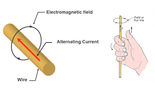
Figure 1. The direction of the electromagnetic field produced around a wire carrying an alternating current I is determined by the right-hand rule.
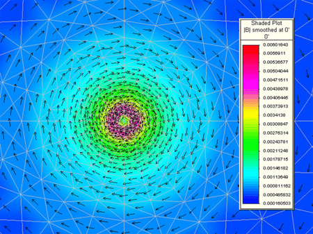 Figure 2. A typical FEA plot of the electromagnetic field generated around a conductor carrying an alternating current.
When the generated changing electromagnetic field tries to pass through an electrically conductive material, each line of flux produces a circulating eddy current in the material as shown in Figure 3. The induced eddy currents generate an equal opposing field that cancels out the field trying to pass through it. The result is no net field through the material. With the amplitude and direction of each individual eddy current, the circulating currents within the electrically conductive medium internally cancel each other out, and the net effect is an induced current that flows around the perimeter of the material as shown in Figure 4. The induced current flow around the material results in the watt generation that heats the material. The amount of watts generated in the material is equal to the actual current flow (in amps) squared times the resistance of the path (in ohms) through which the current is flowing. This is referred to as I2R heating.
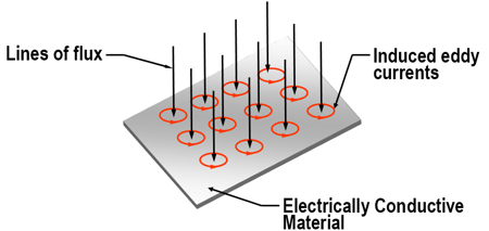
Figure 3. Each line of flux trying to pass through a conductive material generates an eddy current in the conductive material that produces an opposing field to cancel out the original field.
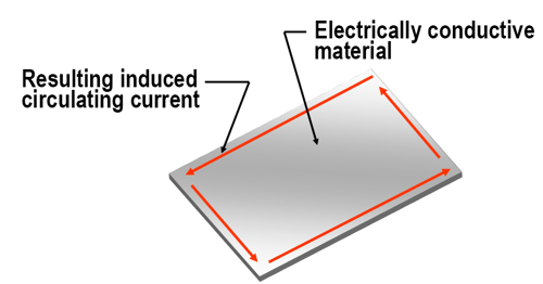 Figure 4. The internal eddy currents cancel each other out because, within the material, the circulating currents are equal in magnitude but opposite in direction. The result is an induced current that flows around the outer perimeter of the conductive material with no net field through the material.
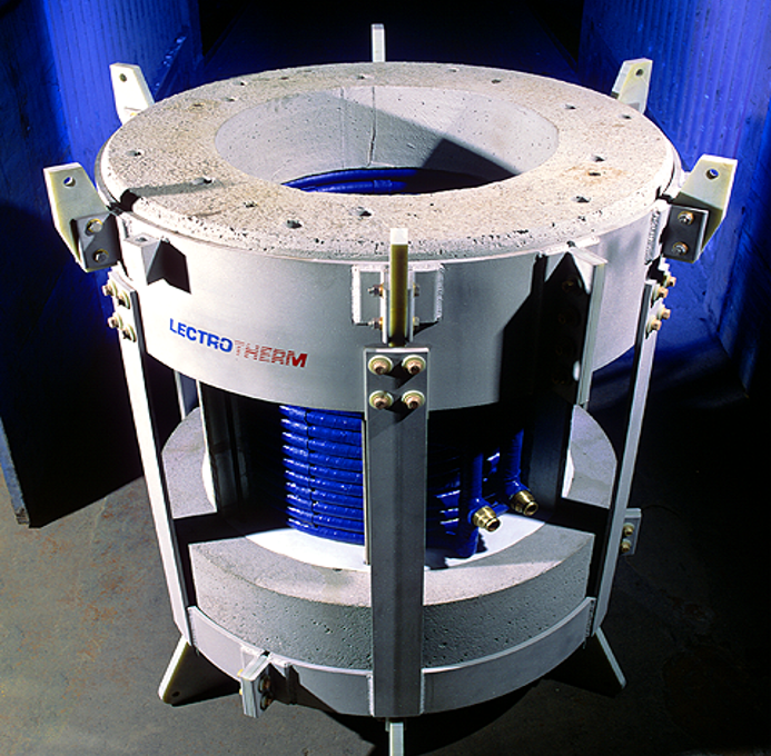
In a coreless induction furnace, the electromagnetic field is generated by a solenoid design induction coil. This coil is typically manufactured with a copper tube wound with a carefully selected tubing profile and a number of turns on the coil to match the process into the power supply used. (Refer to Figure 5 for a picture of a typical coreless furnace induction coil assembly.) It is manufactured from high electrical conductivity copper tubing for low power transmission resistance within the coil to minimize I2R losses. The tube profile has a hollow center for passing low-conductivity water. This water is used to remove both the generated I2R losses in the winding, as well as the thermal energy conducted from the hot metal through the refractory system back to the winding.
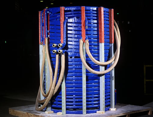
Figure 5. A typical solenoid induction coil assembly used in a coreless induction furnace.
When an AC voltage is applied to the coil terminals, an alternating current passes through the coil winding. The current in each turn generates an electromagnetic field around it as shown previously in Figures 1 and 2. With the turns stacked, the solenoid coil produces an electromagnetic field as shown in Figures 6a and 6b.
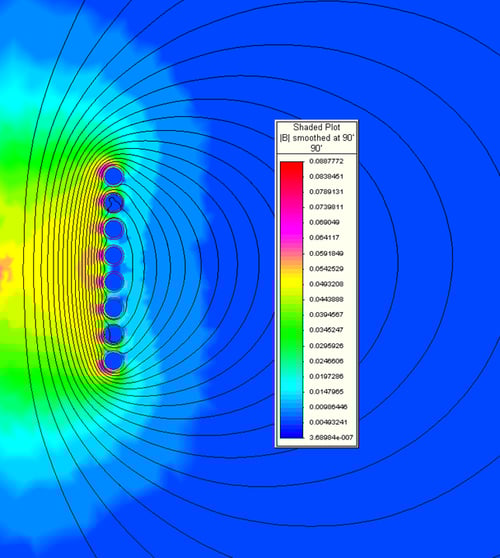
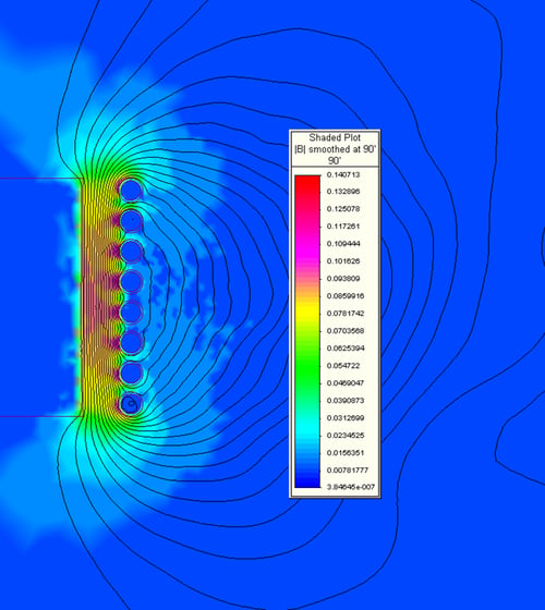 Figure 6. Finite element plots of the electromagnetic field generated by a solenoid-type induction coil. Figure 6a is the field generated with no load in the furnace. Figure 6b is the field with a load inside of the furnace.
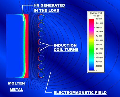 Figure 7. An FEA plot of the electromagnetic field and the energy transferred to the load.
When a load (electrically conductive material) is placed inside of the coil, the field that tries to pass through it induces eddy currents within it that cancel out the field as shown in Figure 6b. This is accomplished through the same principle as previously discussed and shown in Figures 3 and 4. The result is an induced current flowing around the outer perimeter of the load. The amount of energy transferred to the load is equal to the induced current squared times the resistance of the path through which the current is flowing (I2R). Figure 7 shows the transferred energy density in a typical coreless induction furnace. The load in this case is the molten metal within the furnace crucible.
The Coreless Induction Furnace For Investment Casting
Since investment casting can occur with the melting process taking place in either a vacuum chamber or at regular atmospheric pressure, there are many types of coreless induction furnaces used in the process. In any case, the principles of how induction works are still the same. In general, the furnace will consist of an induction coil, a replaceable refractory system with crucible, and a semi-permanent refractory top and bottom with tie rods. Depending upon the capacity of the furnace and the pouring mechanism, the support structure for the furnace may vary. In general, the induction coil provides for the support of the molten metal and the refractory system. Figure 8 shows a general cross-section outline depicting the components of a typical induction furnace with a fixed crucible. Figure 9 shows the same for a freestanding crucible furnace.
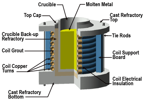 Figure 8. The typical components of a fixed crucible-type coreless induction furnace.
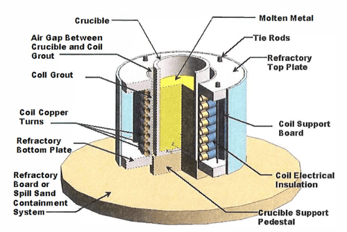 Figure 9. Typical components of a loose crucible-type coreless induction furnace.
The main types of furnace assemblies used for investment casting can be either just a coil with refractory top and bottom, a hand tilt furnace, a lift coil furnace with a freestanding crucible, a rollover-type furnace, or a box-type furnace which can be either hydraulic tilt or hoist tilt. The application will dictate the type of furnace that will be necessary. Figures 10 through 12 show a few different styles of furnaces used in investment casting.
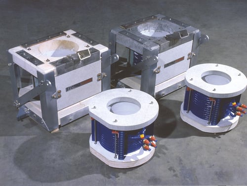 Figure 10. Box and open-type furnaces.
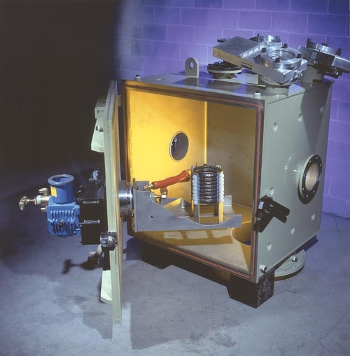 Figure 11. A melt coil shown in a vacuum chamber.

Figure 12. A small open-type furnace.
Typical System Components
A coreless induction furnace consists of a complete system of components necessary for proper, reliable, and safe furnace operation. The main components required are a furnace, power supply, power transmission system (bus and/or water-cooled cables), and a water cooling system. Optional equipment may be required such as a hydraulic system for hydraulic tilt furnaces, and possibly a computer control system for automated teach pouring, system control and monitoring, as well as data acquisition and storage. Refer to Figure 13 for an overview of the typical components of a coreless induction furnace system.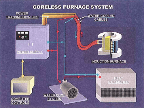
Figure 13. The typical components of a coreless induction furnace system.
Selection Of Furnace Size And Power Rating
The capacity of the furnace is usually determined by the size of the pour required, but there are times when a furnace capacity may need to be larger than the pour size. The size and shape of the charge material to be melted can require a larger opening in the furnace. If borings, turnings, or chips are to be melted, the furnace may require an adequate residual molten heel left in the furnace in order to efficiently melt. Another factor that can influence furnace size is power density. If the required melt rate requires a power level that can result in excessive molten metal meniscus and stiffing velocity, the furnace capacity may need to be increased.
It is important to select the proper power rating for the system. There are many factors that influence the selection of furnace power. The first is the capacity to be melted and the desired melt cycle time. To raise the temperature of a solid material to the pouring temperature, energy must be put into it based upon the characteristics of its solid-specific heat, latent heat of fusion, and liquid-specific heat. The latent heat of fusion is the energy required to push the material through its phase change from the solid to liquid state. Figure 14 shows a graph of several metals and the energy required to raise their temperature from 70°F.
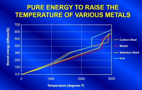 Figure 14. Graph showing the energy required to raise the temperature of several different metals.
The total net energy that is required in the load for the process is simply the pounds of metal to be melted multiplied by the change in stored energy of the metal as shown in Equation 1. The amount of instantaneous net power is the net energy divided by the melt time in seconds as shown in Equation 2.
(Equation 1) kW· sec = W x S
Where kW sec= the total net energy in kW-seconds
W= weight of the material to be melted in pounds
S=the stored energy of the material (kW-seconds per pound) from graph in figure 14.
(Equation 2) kWnet = kW·sec/T
Where kWnet = the required instantaneous power to the load
T= desired total melt time in seconds
Under ideal conditions, the total power rating of the melting system would be the result calculated in Equation 2. Unfortunately, there are many factors that contribute to energy losses in the melting process, such as thermal radiation from the melt surface, thermal conduction through the refractory system removed by the water in the induction coil, I2R losses in the coil winding, as well as I2R losses in the power transmission bus and cables.
Therefore, the total supply output energy required is the net energy to the melt plus the sum of all of the losses in the system as shown in Equation 3.
(Equation 3) kW sys= kWnet + thermal losses + coil losses + transmission losses
From review of Equation 3 it can be seen that for proper system design the following must be taken into consideration:
- Design the induction coil to maximize coupling efficiency (minimize coil losses)
- Design the bus and cables to minimize transmission losses
- The design must take into consideration the size of the furnace and its thermal losses. An improperly designed system that has an undersized power supply will drastically reduce the efficiency of the overall system and reduce the pounds of metal that can be melted per kWh applied. This could, in extreme cases, result in the inability of the system to reach the required pour temperature. The larger the furnace, the higher the thermal losses.
Selection Of Induction Frequency
The frequency affects both the coupling efficiency of the electromagnetic field to the charge and the stirring characteristics of the molten metal in the furnace. For optimal furnace performance, the selection of the system operating induction frequency is very important. There are several factors that weigh heavily in selecting the proper frequency for the application. These are as follows:
- The physical size of the pieces of material to be melted
- The electrical resistivity of the material to be melted
- Whether the furnace will be operated to melt from an empty crucible or with a molten heel left in the furnace
- The geometry of the crucible used in the furnace to contain the molten metal
- The desired molten metal stirring characteristics
The depth at which induced current flows in an electrically conductive material, as shown in Figure 15, is a function of the resistivity of the material and the induction frequency. The following equation can be used to approximate the depth of the induced current (d2) in a material with a resistivity of r0 operating at a frequency (f):
(Equation 4) d2= 3160 x (r0 / f)½
Where d2 is the induced current depth in inches
r0 is the resistivity of the electrically conductive material in Ohm-inches
f is the operating induction frequency in Hz
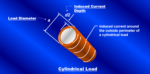 Figure 15. Induced current depth (d2) in a cylindrical load with a diameter (a).
Figure 16 shows a graph of the approximate induced current depth in ferrous alloys at various induction frequencies for both a solid piece of electrically conductive material above curie temperature as well as for the molten condition.
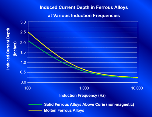 Figure 16. Induced current depth in steel alloys for various induction frequencies.
The induced current depth is extremely important in frequency selection because the electrical efficiency of the system is a direct result of how well the charge material couples with the electromagnetic field. The better it couples with the field, the more efficient it will be. The optimal coupling efficiency of a furnace can be determined by calculating its a/d2 ratio. This ratio is the diameter of the part to be melted divided by the calculated induced current depth. The higher this ratio is, the better the coupling efficiency of the furnace. Figure 17 is a graph showing the coupling efficiency factor for an induction furnace versus its a/d2 ratio.
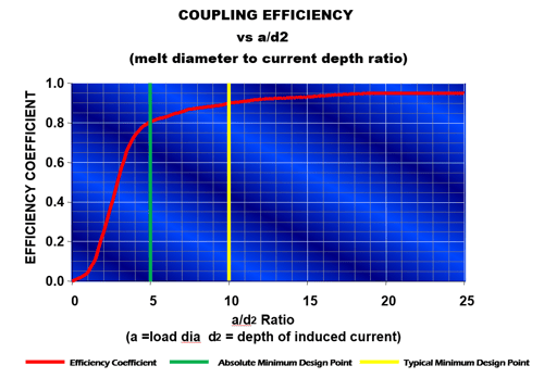 Figure 17. Coupling efficiency factor vs a/d2 ratio.
From review of the graph in Figure 17, it is evident that the a/d2 ratio should always be greater than 5 on a system and preferably no less than 10, if possible, to keep efficiency high. As an example, in review of the graphs from Figures 16 and 17, to heat a solid cylindrical pre-alloyed steel bar in a furnace at 3000Hz shows that the current depth is 0.38". For an a/d2 ratio of 5 the bar diameter should be no less than 0.38" x 5 or approximately 1.9". For the same furnace operating at l000Hz the bar should be no less than 0.66" x 5 or 3.3". Due to this, it can easily be seen why most investment casting furnaces operate between 1000 and 3000Hz. For the same reason, it can be determined why it is impossible to directly melt chips, borings, or turnings using induction. If chips, turnings, or borings are to be melted in an induction furnace, the a/d2 ratio will be close to zero with no coupling efficiency. Therefore chips, turnings, and borings must be melted with the assistance of a molten heel. In the case of a molten heel, the melt diameter in the crucible can be used as the load diameter (a) when calculating the a/d2 ratio, thus increasing the coupling efficiency for a reasonable chip melter.
There is an alternative to the heel melting method of chips through the use of an electrically conductive crucible. In the case of an electrically conductive crucible, the crucible is heated by induction and the energy is transferred to the load material through conduction and radiation. If an electrically conductive crucible is to be used for an application, it is important that the chemistry of the crucible and the molten metal contained within do not react to adversely affect the process.
Forces And Stirring Of The Molten Metal
The force acting on a current-carrying conductor is related to the current in it, the flux density, and the length of the conductor as shown in Equation 5. Since current flows in the coil winding and an induced current flows in the opposite direction on the outside of the load, a force is generated that acts on each. The result is a squeezing or pinching force acting on the molten bath. An equal and opposite radial force pushing out on the winding also occurs. Figure 18a shows the inward squeezing force acting on the molten metal. This inward force is usually greatest on the melt near the center elevation of the coil. The metal is pushed inward towards the center of the bath. At that point, the molten metal will flow up from the center to the top of the melt as well as down the center to the bottom of the melt. This results in the conventional "quadrantial" stirring pattern of the molten metal that is associated with coreless induction furnaces as shown in Figure 18b.
(Equation 5) F= I x B x L
Where I is the current in the conducting medium
B is the flux density where the current is flowing
L is the length of the conductor
F is the resulting force on the conducting medium perpendicular to both the current and the field
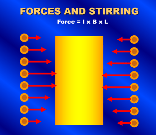
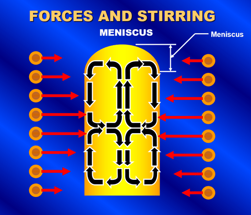 Figure 18. A squeezing force acts on the molten metal due to the induced current in the metal and the electromagnet field as shown in Figure 18a. The result is a quadrantial stirring pattern of the molten metal and the formation of a meniscus as shown in Figure 18b.
The amount of stirring is characterized by the velocity of the molten metal circulation as well as the resulting height of the molten metal meniscus. Both the velocity and meniscus are affected by the inward squeezing force. The force will increase with increased power and decrease with increased frequency. The graph in Figure 19 shows a plot of the approximate forces associated with an investment casting furnace netting 150kW into a 275-pound molten ferrous load. Contrary to many people's beliefs, the molten metal meniscus at the surface of the molten bath is not formed due to the velocity and direction of the molten metal flow. It is actually formed by the relationship between the inward squeezing force generated by the electromagnetic field on the molten metal versus the outward pressure due to the molten metal head. Where the outward head pressure is less than the inward pressure from the electromagnetic field, the metal does not contact the refractory walls. The graph in Figure 19 shows that operation of this furnace at 1000 Hz would result in a molten metal meniscus height of approximately 2.5". The same furnace operating at 3000 Hz would produce a molten metal meniscus near 1.3". It is very important in the design of the melting system to make sure that excessive forces are not applied to the furnace. It is conceivable that the molten metal in the furnace could be levitated within the crucible if a high enough power level was applied at the right frequency.
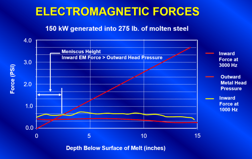 Figure 19. A graph showing the forces on a 275 lb. steel capacity furnace netting 150kW into the molten metal. The crossover point defines the height of meniscus.
Conclusion
We have shown that there is a diverse set of factors determining the operation of an induction system for investment castings. A good basic knowledge of how induction works and an understanding of how it relates to the intended process will aid in the selection of the right system for any investment casting application. Coreless induction furnaces are great tools for the melting of metals for investment casters, and with proper equipment selection, they will continue to be the mainstay of precision casting processes for many years to come.